A huge shout-out to those who got the new projector up and running in time for our monthly movie nights. We here at the Co-Lab Does Committee (CDC) are really appreciative of all of the hard work of the members who researched, proposed, and then installed something the whole lab is going to have fun using.
To that end, we would like to continue to announce the monthly movie nights that occur at 7pm every first Saturday of the month in the center room of the lab. Come enjoy popcorn, company, and nerdy movies with all your friends at the Co-Lab and whoever you would like to bring.
Watch the public mailing list for a monthly poll of the movies!
David Hinkle will be teaching a leatherworking class on Saturday, May 10th after the meeting (So about 2pm). The class will cover the basics of laser assisted leather working. There will be a $10 charge to cover materials. During the class you’ll make a small QC Co-Lab key chain with a tooled logo. You’ll learn about cutting (With the laser), dying, tooling (With laser assistance), stitching and riveting leather. This will give you the basic skills needed to get started on pretty much any leather working class at the lab. Class is open to all, QC Co-Lab membership not required.
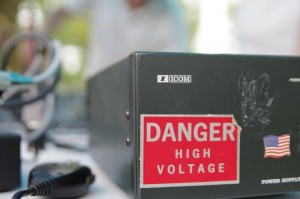
This year the QC Co-Lab will be participating in Amateur Radio Field Day from Saturday, June 22nd at 12:00 PM through Sunday, June 23rd at 12:00 PM. Ham Shacks were some of the original hackerspaces, so it only seems fitting to have one here.
Field Day for us kicks off at noon and hopefully runs for 24 hours. Amateur Radio operators all over the world will be getting together to make contacts, practice emergency protocols, and generally promote the hobby. If you have ever been interested in Amateur Radio, stop by Saturday. It is an excellent time to learn more about radio communication and possibly even get on the air. We hope to have a couple stations up, and if the weather permits talk to some satellites, or even the International Space Station.
More information about Field Day is on the Amateur Radio Relay League (ARRL) website at http://www.arrl.org/field-day.
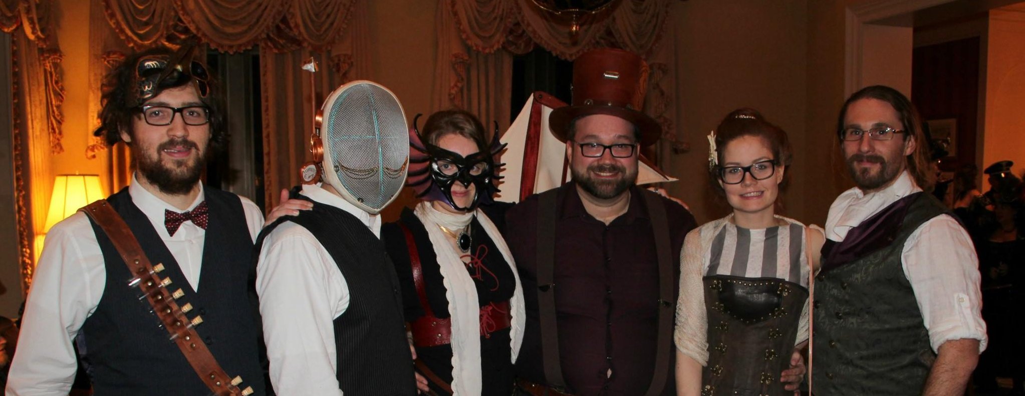
The Putnam Museum is throwing a Mad Scientist Ball to help fund their new STEM (Science, Technology, Engineering, and Mathematics) Learning Center on Saturday, May 18th at 7:30 PM. The Putnam is helping to energize the Quad Cities and build more awareness about the STEM community, and are hoping to put together a fantastic set of exhibits for our community. When the QC Co-Lab heard about this formal soiree, we knew that we needed to be there.
QC Co-Lab president David Hinkle and secretary Cody Wilson will be in attendance at the ball. According to the invitation, the dress for the event is “Cocktail attire, Lab Coats encouraged.” We plan to take this instruction literally. We’ll be sure to post an update after the ball detailing the event.
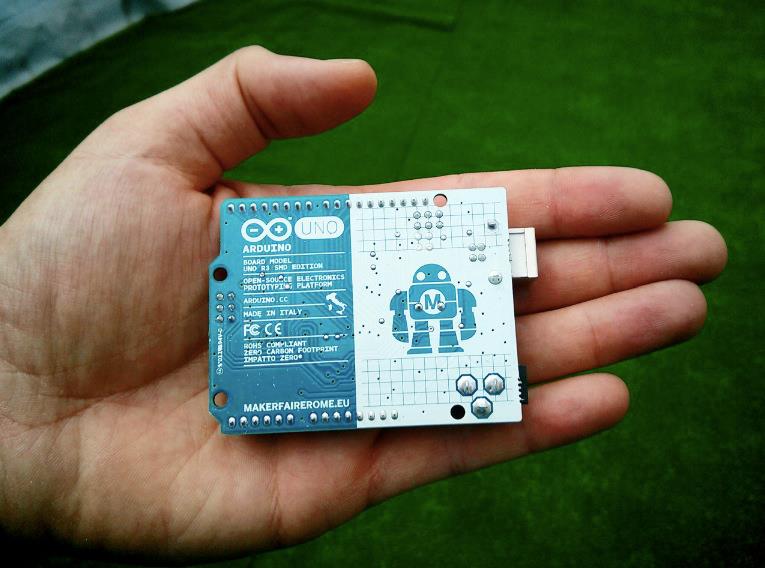
Come learn basic programming skills on the Arduino platform with the QC Co-Lab!
David Hinkle, QC Co-Lab President and self-proclaimed “pretty good programmer” is hosting an Arduino programming class with a focus on robotics automation. This class will start on Saturday, May 25th, 2013, and span 4 sessions held weekly from 2 to 4pm. Each session has a suggested donation of $10, payable either online at our donations page, or at the QC Co-Lab. According to Dave, the topics the class will cover over the 4 weeks:
Basic digital electronics. What is Volts, Current, and Resistance What are pullup and pulldown resistors. Ohms Law. Various forms of pulse width modulation.
Basic programming. Variables, functions, using libraries. Making stuff do stuff.
Basic hardware control. Servo’s, steppers, electronic speed controls, LED’s, interfacing with off the shelf RC electronics.
User requested content.
The user requested content can range to anything related to Arduinos, robotics, and micro-controller computing. Feel free to contact David before the class at [email protected] with your suggestions.
You will want to have an Arduino Uno or compatible development platform for this class. A limited amount of Arduino Unos are available at the QC Co-Lab for $35, and can be purchased before any session as supply remains.
This Saturday, April 27 from 10 am to 4 pm, join the QC Co-Lab as we head up to the Lindale Mall for the Cedar Rapids Mini Maker Faire! We’ll be showcasing a myriad of projects that embrace the STEAM (science, technology, engineering, the arts, and mathematics) and/or maker philosophies, such as quad copters, a Ruben’s tube, and liquid nitrogen. We’ll also be making the trip with the Co-Labulance, our 1981 Chevrolet G30 de-commissioned ambulance / mobile hacking rig. Wish us luck as we take her out on her maiden voyage after a considerable amount of maintenance and work was put into her.
If you’d like to check out our 4-table booth, as well as what should be a fantastic showing of making at its finest, head on over to the CR Mini-Maker Faire site at makerfairecedarrapids.com, and click the “Register to Attend” button on the right-hand side of the page to request your free tickets.
This year, one of our members is presenting at Security B-Sides Iowa 2013 in Dubuque, IA. Chris Cooper will be presenting his talk on building “Dynamic Linux Firewalls using IPSet”. If you would like to check it out, his slides are available as well as some example scripts referenced in the presentation.
If you weren’t able to attend, the live stream is available here recorded video will be made available after the show.
Long overdue for an overhaul, and in desperate need of more accessible content publishing capabilities, the new QC Co-Lab site should be a refreshed, and revitalized site for publishing the goings on here at the Quad Cities’s First Makerspace. Feel free to check out the new site, and send feedback to [email protected].
First up was getting the redesign finished, and important content transferred over. Additional content from the old site will be available at old.qccolab.com until it is migrated over to the new site.
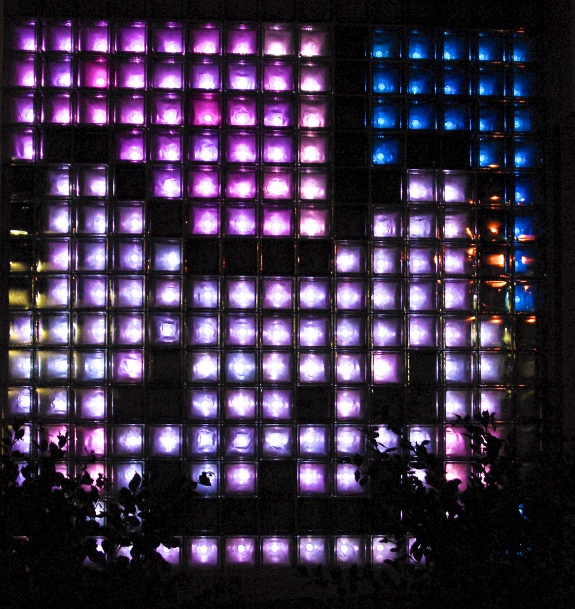
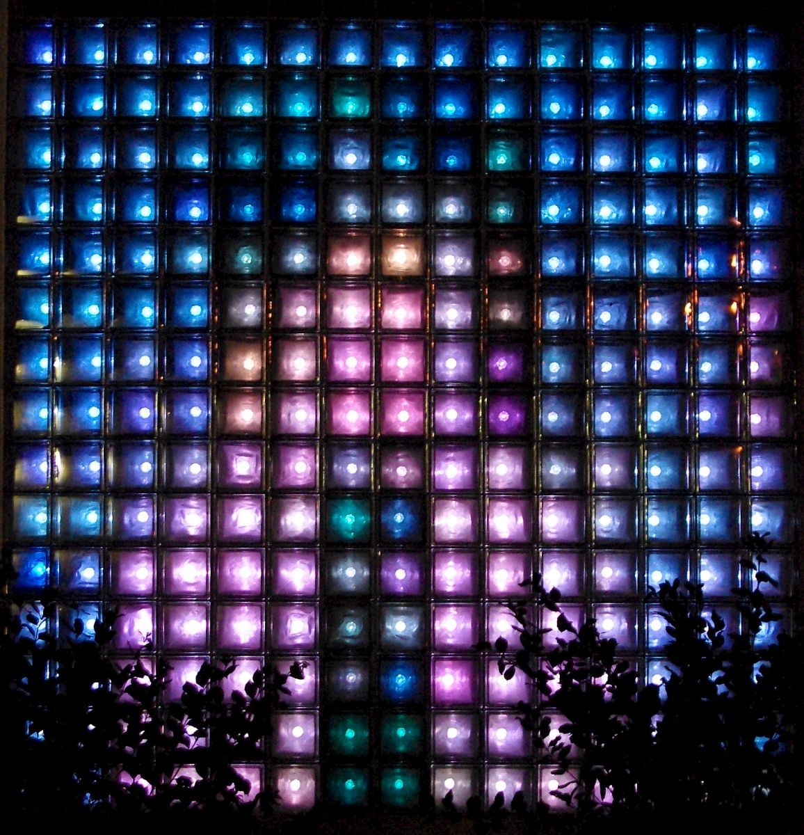
For some time now, the QC Co-Lab has been working on transforming the North wall of our space into a programmable display awesome enough to put our hackerspace on the map. For those that want to just cut to the chase, you can jump straight to our code and videos of the wall in action, otherwise read on to hear our story.
Located in the heart of the Midwest, we sit between some of the biggest names on the US hackerspace map. TCMaker to the North West, Pumping Station One to the East, ArchReactor to the South, and CCCKC to the South West. With such big names all around us, we were really going to have to do something special to make our mark.
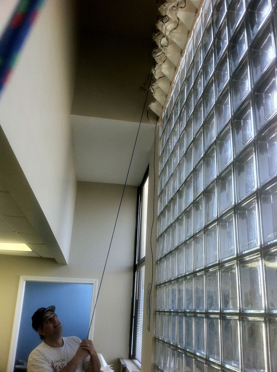
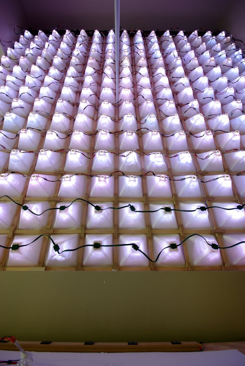
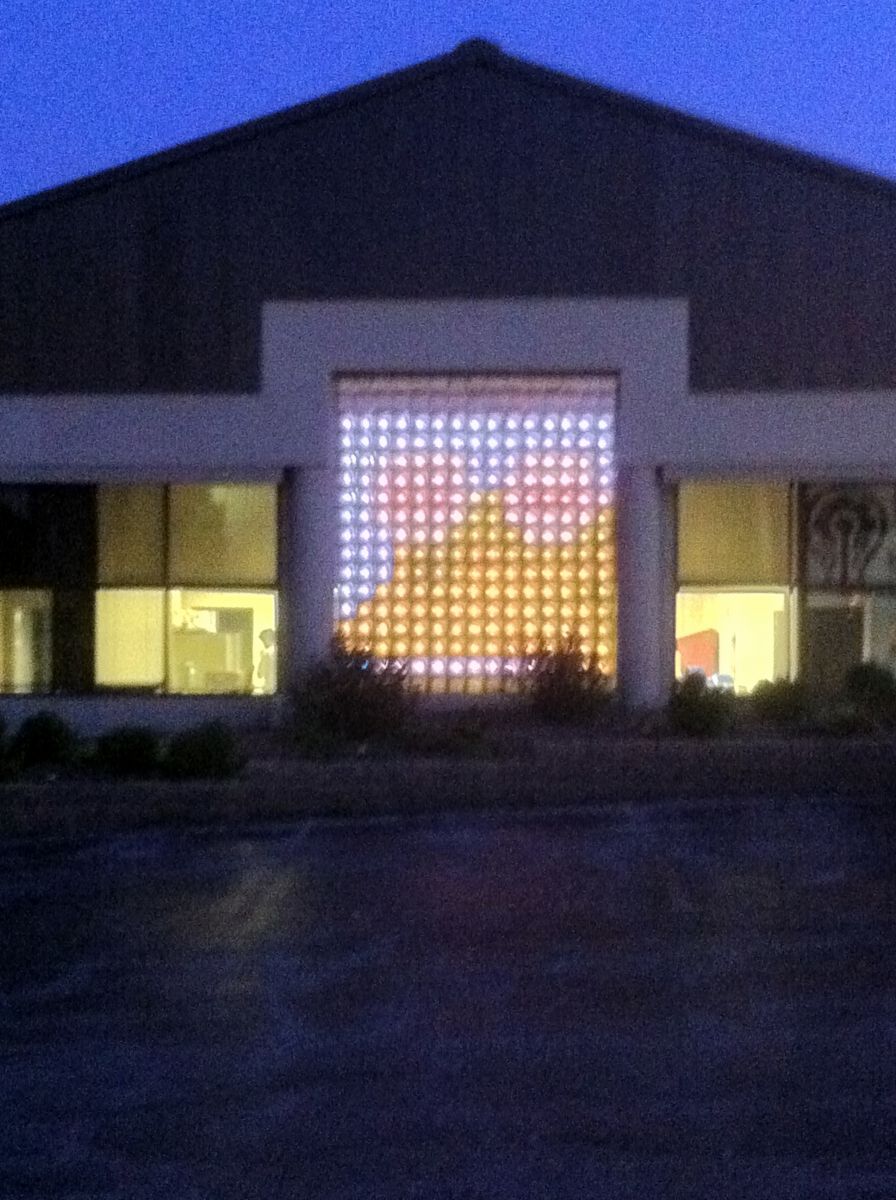
On the north wall of the QC Co-Lab, there is a 15×17 glass block wall facing a major city thoroughfare.
When we were searching for the making of our first big project, the thought hit us; those 8” blocks would make perfect pixels in an LED display! So we dug in and started researching our options.
We looked around at several solutions, including the BlinkM and ShiftBrite, but we quickly ran into an issue, at 255 pixels, the costs were adding up quick. We decided that we would need to wait to raise some funds and see if we could find another option.
In November of 2010, an enterprising hacker named Darco (Robert Sun Quattlebaum), stumbled upon a little secret that took the hacker community by storm. He discovered the hidden secrets of GE Color Effects Christmas Lights. A few days later, one our our members, Ben Ziegler, managed to pick up two strings to play with during the QC Co-Lab Holiday party.
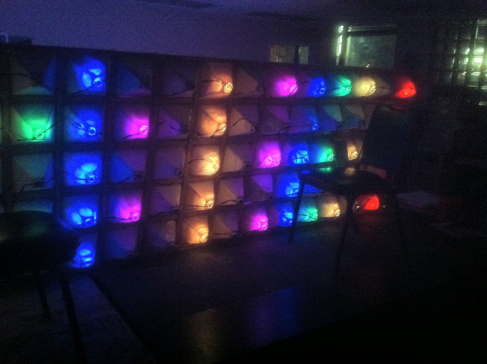
Taping lights directly up to the glass, the lights were bright enough, but we wanted a solid block of color. A regular QC Co-Lab visitor, Josh Conroy, built some reflectors out of cardboard triangles coated with spray adhesive and aluminum foil. They were built into pyramids with duct tape. By bending the tips inward at the peak the cardboard kept the bulbs in place. We assembled the first 36 light string into two 3×5 sets using some ceiling tile frames with a fluorescent light diffuser in front to get a solid color wash.
With the help of member Don Kieu, we got a modified version of Darco’s initial Arduino code running and the timings worked out. Using a 3×5 pixel font Josh made, we had a two character scrolling marquee, and more importantly, a solid idea for moving forward. We thought that if we could catch an after-Christmas clearance sale, these lights would be a cheap and awesome way to fill out our lightwall. The problem was, it seemed like everyone else had the same idea.
While searching from store to store looking at ‘Sold Out’ signs, we noticed an overlooked gem: GE Color Changing Snowflakes!
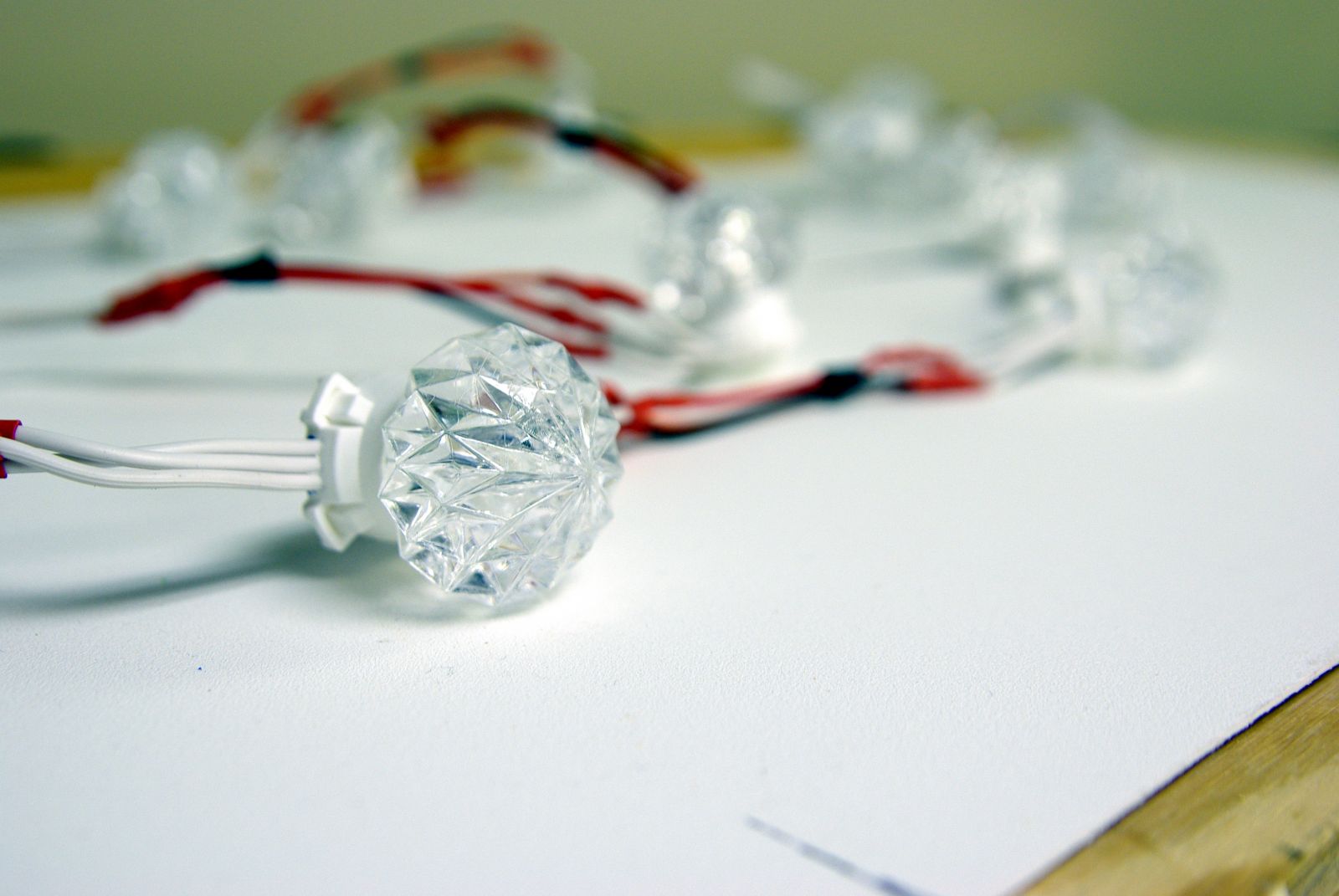
These use the same bulbs as the strands everyone else was using, but in a different form factor. We quickly bought up the last 5 sets we could find and started unlocking their secrets.
Phase 2: Initial Testing
With our stack of lights in hand, we started dismantling them and trying to scale up our earlier success. Since we had a plethora of dead power supplies and old AV cable lying around, we decided to salvage some old RCA jacks and 4-pin Molex power connectors to make everything modular. Since our target wall was 15×17, we decided to chop our lights into modular 15 LED strands. We also built some splitters to allow us to use the stock 5v transformer for powering both the lights and an Arduino.
It wasn’t long before we had these modular strings up and running. We had some fun playing with the colors and building some basic test patterns.
It was about this time that the scale of our project started to sink in. The addressing in the lights allowed for 63 lights per string. Because we broke everything into rows of 15, this meant a maximum of 60 lights, or 4 rows, per string in our final design.
Up to this point, all the code we worked with was designed to power a single strand of lights, not five, which meant we were going to have to redesign our code from the ground up. To rebuild it, we needed to know these lights inside and out, so we started researching. Most of our information came from Darco’soriginal post (and comments) and the Do it yourself Christmas forums.
I strongly encourage anyone wanting to work with these to read both those threads, as they have excellent information about the inner-workings of these lights, specifically Darco’s analysis of the protocol. Assuming you have at least read Darco’s post, here are some additional details we thought were worth noting:
If the brightness is changed by more than a single bit, the lights flicker a bit, so single bit brightness changes are required for smooth fades.
The lights are self clocking based off the falling edge. The sample appears to be taken half-way between clocks, meaning there is some play in the timings.
The stock clocking is based around 30 μSeconds, with the first 10 μS always being low, and the last 10 μS always being high. The middle 10 μS is the “data” bit and is inverted. This means 10 μS low, 20 μS high for a “0”
The DigitalWrite() function in the Arduino has roughly 7 μS of overhead, making it impractical for our use (given our 10 μS timing needs)
The stock Delay() functions in the Arduino are not accurate enough for our use.
The Lights are self-addressing at startup, so the physical order isn’t that critical.
Along with the research, we started doing the math on the timings. At 840 μS to address a single bulb, writing to all 255 one at a time would take 214 mS, leaving us with a jerky 5 frames per second. If we figured out how to write to all five strings at the same time (with 60 bulbs per string), we could do almost 20 FPS. This was better, but it left no time for any processing. We finally settled on splitting our strings in half, giving up 30 bulbs to a string, but netting us a whopping 40 FPS on paper. Running at 30 FPS, this would leave us with 244 mS of processing time between frames. (We put together a fun google docs spreadsheet to help us work out the timings. If you download it, you can play with the timings for yourself. It is available here.)
It was around this time we found out our neighbors, Hamilton Technical College, were going to have an open house in a few months. This meant a lot of foot traffic right outside our space in about a month. If we could have the lightwall finished in time, it would be a great chance to introduce some people to the hackerspace community. Since we knew the timings would work and had our string layout finalized, we decided to split up the project to get it done in time. Part of the team started on the code, while others went to work on mounting.
Phase 3: The Code
With the math done, we knew the wall would work in theory. We just needed a way to talk to it. Our plan relied very heavily on the ability to write to 9 strings simultaneously. We considered the Arduino, since we used it in our initial testing, but with only 16 MHz and 2K of RAM to work with, we quickly discounted it and looked for something else.
We started looking into various development boards and even a dedicated x86 PC to run it. We figured it would be a quick job for David Hinkle, a member and veteran Linux programmer, but was unfortunately tied up with work and didn’t have the free time to help with the project. With our deadline fast approaching, we decided to give the Arduino another go. We figured we could use if for a simple display, then move to a bigger platform later.
The big challenge we had now was how to write to all nine strings at once. We started trying to interleave our writes, using the 10 μS between state changes to manipulate the other strings. DigitalWrite had a horrible 7 μS overhead. Even DigitalWriteFast wasn’t fast enough. At 16 Mhz, we only had about 17 CPU cycles per string to work with. As we were looking for ways to speed up the code, Mark Kruse discovered Port Manipulation, a way to write to a whole register at the same time. This would give us a speedy write, but we still needed a way to process nine strings worth of data at the same time.
The following evening, we sat around trying to find a way to use our new-found trick. In a caffeine-induced moment of inspiration, we had the answer! What if we did all the processing ahead of time on a PC, so all the Arduino had to do was pump raw data directly into the register? If we cut out our last half-string, leaving us with a 15×16 lightwall, our data would fit into conveniently sized 8-bit chunks. If we write to the same address on all eight strings at once, all that would need to be transferred is a 12 byte long chunk of interlaced color data.
We originally wanted to use the bottom half of the Analog register and the top half of the first digital register, then have a PC stream the raw data over the serial link. After the first few trial runs, we ran into an issue with the Analog pins. While writing directly to the Digital pins was quick and responsive, the Analog pins we a bit unpredictable. Sometimes they would push the data just fine, other times they would mangle the signal resulting in a rainbow of random colored flickers that would make Nyan Cat jealous. The more we thought about it, the less we liked the idea of being tied to a PC. We decided to just bite the bullet and use the whole first Digital Buffer.
Using the entire first Digital buffer was great, since we no longer had to split up the data while writing. The down side was we lost our serial link: our best source of debugging information. Fortunately, we just made a giant wall of lights we could communicate with, so an error code function was crafted and we moved on.
Somewhere along the line we found an SD shield we could use to store the data on. We decided to use the Fat16 libraries, since they used almost half the ram of the Fat32 library.
Since we now had up to 2GB to work with, we decided to come up with some sort of file format, so anyone could go and create an animation to display. Being a networking engineer by trade, I’m a sucker for a good, flexible, protocol. Since I was doing most of the base code writing at this time, I decided that we would make an expandable file format, capable of many different types of animations. In hindsight, it may have been a little overkill, but hey, what’s the point if you can’t have a little fun, plus it made a great learning opportunity. For the initial release, we decided on just supporting a raw data stream format, but several other formats are in the works.
In the spirit of modular code, and knowing that not everyone would want to use just our player, we broke the lightwall manipulation portions into their own class library. We also cleaned up the code and made supporting additional message types easier down the road. You can find our lightwall library and the associated player on Github: https://github.com/CCDKP/QC-Co-Lab-Light-Wall
Now that we had a player, we needed a way to make files to play on it. Because most of the processing is done on the PC, the routines for saving and loading are kind of ugly. Colors need to be cut down to 12 bit, the data needs to be inverted, and the pixel data needs to be interleaved across multiple rows at the same time. In another late night programming session this chunk of psuedocode found its way to the whiteboard:
The top half is for saving, the bottom for reading the file back in. The code would be repeated two more times for the green and red color bits. Seeing this again, I can’t help but feel slightly responsible for the passing of Dennis Ritchie. Ugly as it may be, it worked, and because of it two additional projects were spurred.
The first is a Visual Basic program written by our very own Mark Kruse. It is the full-featured editor, and at this point in time the only tool short of the wall itself that can open and display lightwall files. Check him out here: https://github.com/krusem/LightWallEditor
The second project is a python script by Mark Riedesel. It converts animated gifs or series of PNGs into lightwall files. One particularly entertaining trick is using FFMPEG to convert a video file into a series of PNGs, which can then be used as input for the script. His code is available here:https://github.com/Klowner/8cic-encode
While all this coding was being worked out, the more physically inclined members were working on building something to put all this code to use.
Phase 4: Construction
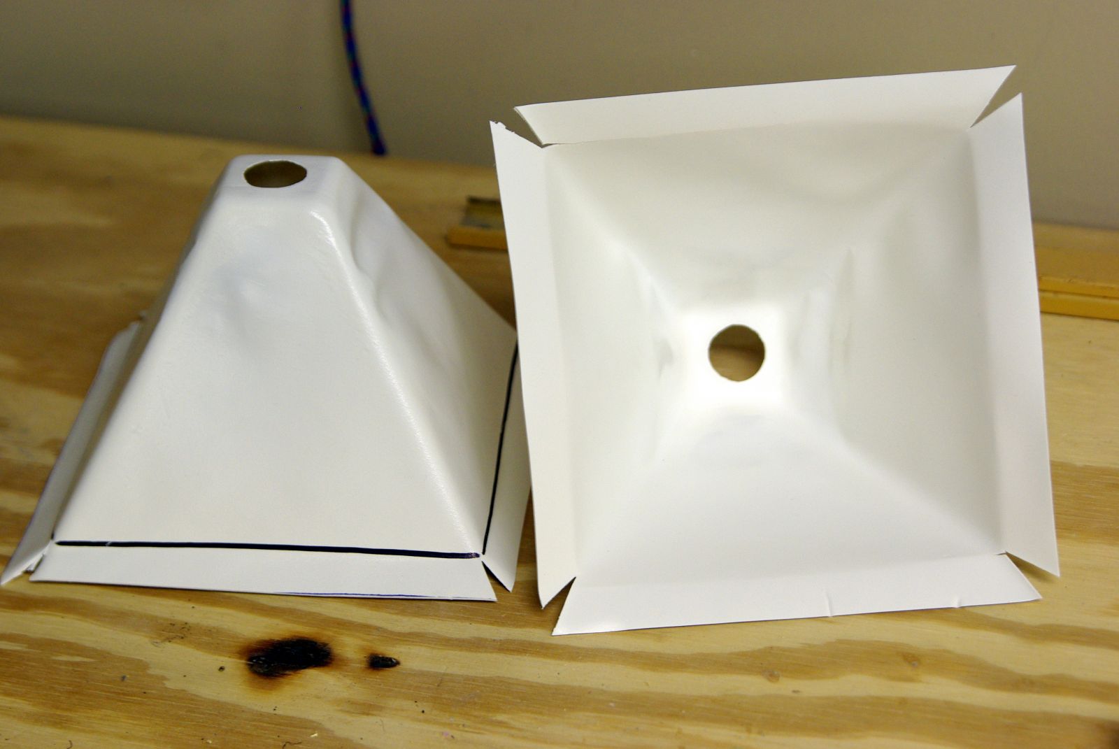
While our initial cardboard cones worked great as an example, they only held up for a few weeks before falling apart. It was clear we were going to need something more durable, and able to support the weight of an 11-foot structure.
Over the course of the week he was here, Josh helped us build more prototype cones out of everything from aluminum pie pans and funnels to wood and plastic, all the time trying to balance cost, reflection, diffusion, and structural integrity. We tried various translucent plastics, parchment paper, and spray-on window frosting for diffusers, and foil, mirrors, and reflective paint for linings. We always kept a string of different prototypes up to let everyone see and comment. Each new idea meant finding parts, calculating cost, constructing, mounting, then waiting for nightfall before running outside the building to compare.
We finally settled on a design built out of white plastic sheet in a pyramid form. The raw materials were affordable sheets of shower lining from the local hardware store. The white plastic was lightweight, sturdy, and reflective enough that it didn’t require additional treatment. The plastic was malleable enough we could use a vacuum-former to mold the pyramids. A flat lip around the outside edge would be used for mounting, while a 1” hole in the flattened tip would hold the lights. We decided to use the plastic diffusers that came on the bulbs, as they doubled as clips to hold the lights in the cones.
The plan was coming together, save the small issue of not having a vacuum-former. Being a hackerspace, however, we didn’t let that stop us!
While the details of the vacuum-former construction is probably best left for it’s own writeup, with the combined effort of Ben Ziegler, Neal Meeker, and Mark Riedesel, we had a functioning machine. Using a fiberglass form build by our president Steve Hamer, and an improvised hole-punch made from some sharpened steel pipe, we are able to start turning out cones.
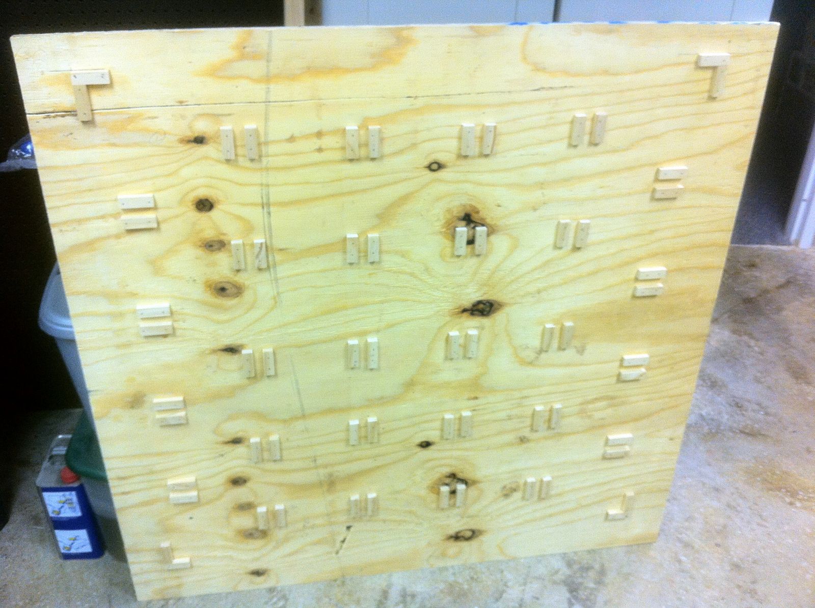
To assist with mounting, Dave Langcamp designed a jig for making interlocking 5×5 lattices out of thin wood strips.
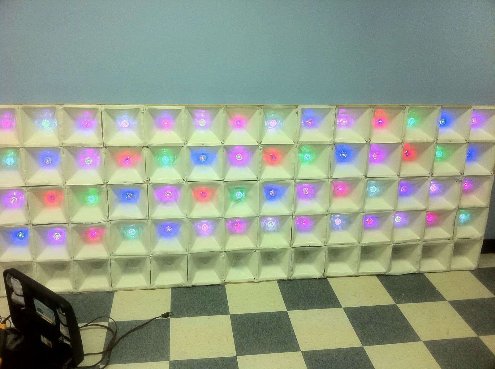
We could staple the cones directly to the lattices, then attach three panels together to make a 5×15 module to hang on the wall. They were sturdy enough to support the whole structure, but light enough we could still hoist them up with some nylon rope and a few eyelets. They were also just small enough that we could break down a couple of them if we wanted to take a section of the wall to a makerfair.
As we started to expand beyond our initial testing strings, we ran into another speed bump. The lights we used for testing up to this point were built for stringing up along the house, and had a nice 10” spacing between bulbs. The lights from the snowflakes we purchased were more densely packed, so they only had 6” of wire between bulbs. Since our glass blocks are 8” center-to-center, this meant we would need to splice a 4” extension of 3-conductor wire between each and every bulb. This project was going to take a serious labor involvement.
In a scene reminiscent of a 1990’s movie montage, 1400 solder joints, 255 vacuum-formed cones, nine wooden frames, three weeks, two small fires and a tube of burn-cream later, we had all the parts we needed to put this project together.
Phase 5: Mounting & Testing
With less than two weeks until the open house, we were getting down to the wire. We attached a few of the frames, stapled in the cones, and wired up all the lights. This was our first chance to bring all the software and hardware together and see what we had worked so hard to build.
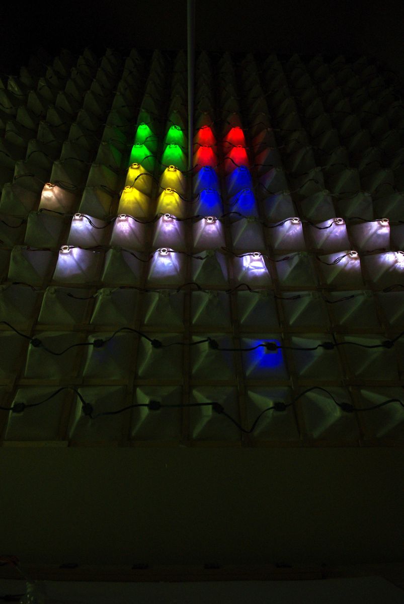
After a bit of fiddling with wires and checking connections, the first segment of the wall sprang to life. A simple binary counter clicked away in a twinkle of dazzling colors.
As we stood back and marveled at our now toy, we noticed the occasional glitch and flicker. Chalking it up to a bug in the counter, we shut the wall down and loaded up our color diagnostics program.
As the lights fired up one by one, we noticed them getting dimmer and dimmer. By the time it got to the last few bulbs, the colors shifted and the program quit running. As we went to check the cabling, we noticed the power brick was really hot! Up to this point, we had been using the original 3-Amp transformers that came with the lights. While it happily supported 75 lights when they were blinking away random colors, when the lights were all a solid white, it could only sustain 3 strands (45 lights). Scaling it up, we figured we would need a 15 Amp power supply to safely power the wall at peak. As it turns out, a 15-Amp 5-Volt power supply is not as easy to find as one might think. We ended up modifying an old PC power supply (Which conveniently matched the 4-pin Molex we were using for connections), and soon we had enough power to light the whole wall at once.
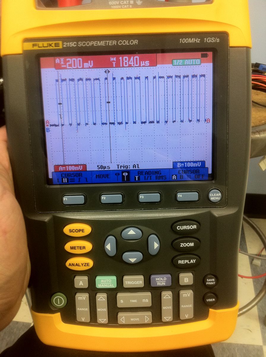
Now that power was no longer a limiting factor, we started to tie together more strings. By the time we had the second module online (150 lights), what started as an occasional glitch soon became a steady nuisance. After borrowing an oscilloscope from work, we saw our timings were a few microseconds off.
After a bit of tweaking, we found that each string had a varying tolerance for the timing. We tuned our code to get as close to the stock 30 μS bits as possible and most of the problems cleared up, but we were still experiencing a small problem that jumped around.
With how far we had come, we refused to be beaten by a little blinking, but it was frustratingly difficult to find. The problem was the inconsistency of the code. Sometimes a bulb wouldn’t update, other times the color would be off or the bulb would be very dim. Every time it would be a different bulb on a different string. There didn’t seem to be an reason to it. After much code review and wiring checks, we finally caught a break and captured a defective packet on the scope
.
Examining the timing, we noticed an extra 3 μS right in the middle of the color data. We had worked hard to insure a rigid 30 μS, so we were confused by this mysterious 33 μS bit. It suddenly occurred to us that our trusty Arduino might have been sabotaging us this whole time. For all the time we spent trying to get our timings absolutely right, we forgot to disable the internal interrupts. Every so often the internal Arduino interrupts would go and run 3 measly microseconds worth of internal house keeping, but it was just enough to throw the timing off on picky bulbs and mess up the packet. One little code tweak later and everything was back in action. The lights were bright, the colors were crisp; it was time to mount the wall in its final home.
Our president, Steve Hamer, decided to brave the heights and climb the ladder to the top of the window and install a couple of eye hooks in the ceiling. After threading through some nylon rope, we attached eye hooks to the back of panels and tied them to the rope. From here we started joining panels together and hoisting them into place. A pair of shower curtain rods served as supports to keep the center flush against the window. After everything was up and mounted, the only thing we had left to do was wait until dusk and see if our months of hard work would pay off.
Phase 6: Display
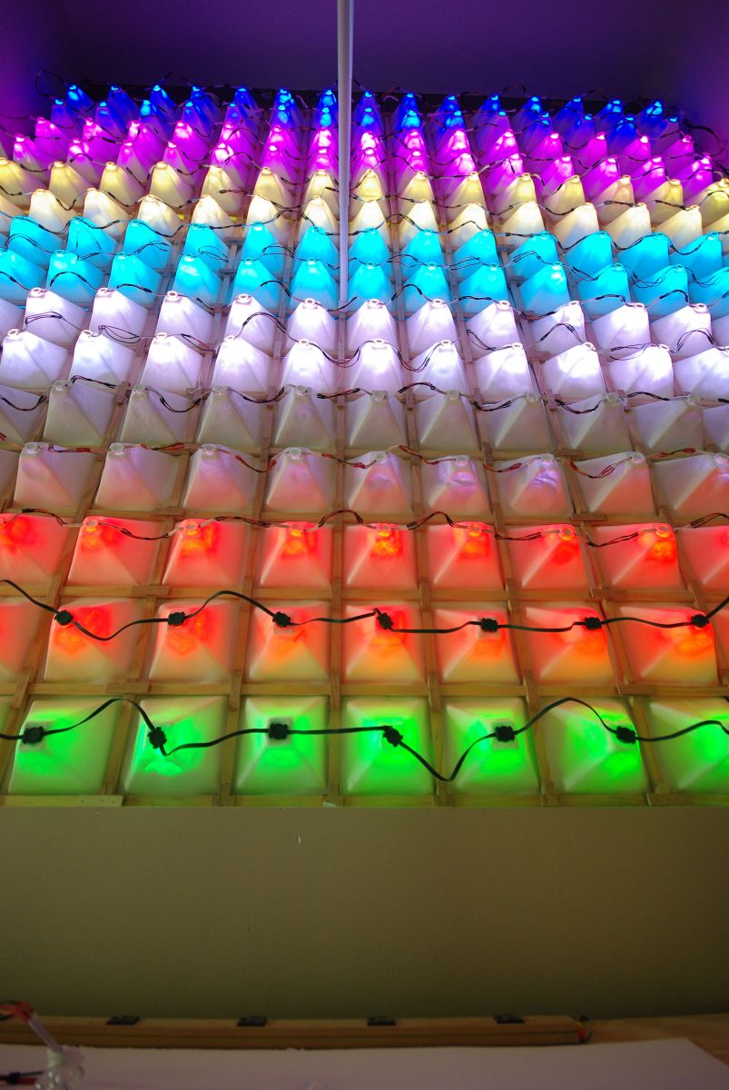
The first night we fired up the wall, there was a lot of excitement. We had talked about this project since we first founded the QC Co-Lab more than a year prior. After months of hard work by many of our members it was finally time to see it in action.
Seeing the wall in action, we were jumping around in the parking lot laughing. The animations were smooth and the colors were vivid. From across the street, you could see the picture perfectly. We had finally completed the QC Co-Lab LightWall. All that was left was to clean up some code and release it for the rest of the hacker community to share.
The Demo routine from inside
All glory to the Hypnotoad!
Simulated Blue Screen & Reboot
Nyan Cat
Never gonna give you up
Phase 7: So Now what?
Getting the LightWall built was just the beginning. Now that the wall is up and running, we have the fun job of making entertaining things to display on it. We have two solid plans for moving forward: expanding the current LightWall display protocol we set up and creating an interactive platform.
When we built the Arduino player to run the wall, we designed a modular system. While we only initially wrote the raw data stream format, plans are in the works to create additional data types, including scrolling text, sprite-based animations, and variable-delay frames. Keep an eye on the project, or feel free to contribute. We built the system as a starting point and really want to see where it can go from there.
The other plan we had was to find a way to make the wall more interactive. The current player is fairly static, due the the limited resources of the Arduino. There has been discussion amongst our member of porting the project to a larger platform, like the Netduino [URL][http://netduino.com/], so we can produce games, and real-time animations involving physics, anti-aliasing, and more.
There is a long road ahead for the QC Co-Lab and the LightWall. We hope the community will get involved and help us take it further than we would have imagined. If you have any questions or comments, we are always happy to hear from you: [email protected]. Thanks for reading.
Core LightWall Team:
Chris Cooper
Steve Hamer
Mark Kruse
Dave Langcamp
Mark Riedesel
Ben Ziegler
Special Thanks
John Abdul-Masih
Keith Claussen
Josh Conroy
David Hinkle
Don Kieu
Neal Meeker
Dustin Saldivar
Cody Wilson
Robert Sun Quattlebaum
The DoItYourselfChristmas.com forum community
& The rest of the QC Co-Lab
Dave Langkamp has been hard at work on this home built Solsylva CNC Machine. He used his expert design and fabrication skills to assemble it, with a little help from members of the Co-Lab on the electronics. Check out his blog to see what he’s been fabricating and how he’s improved the design.